Configuration file
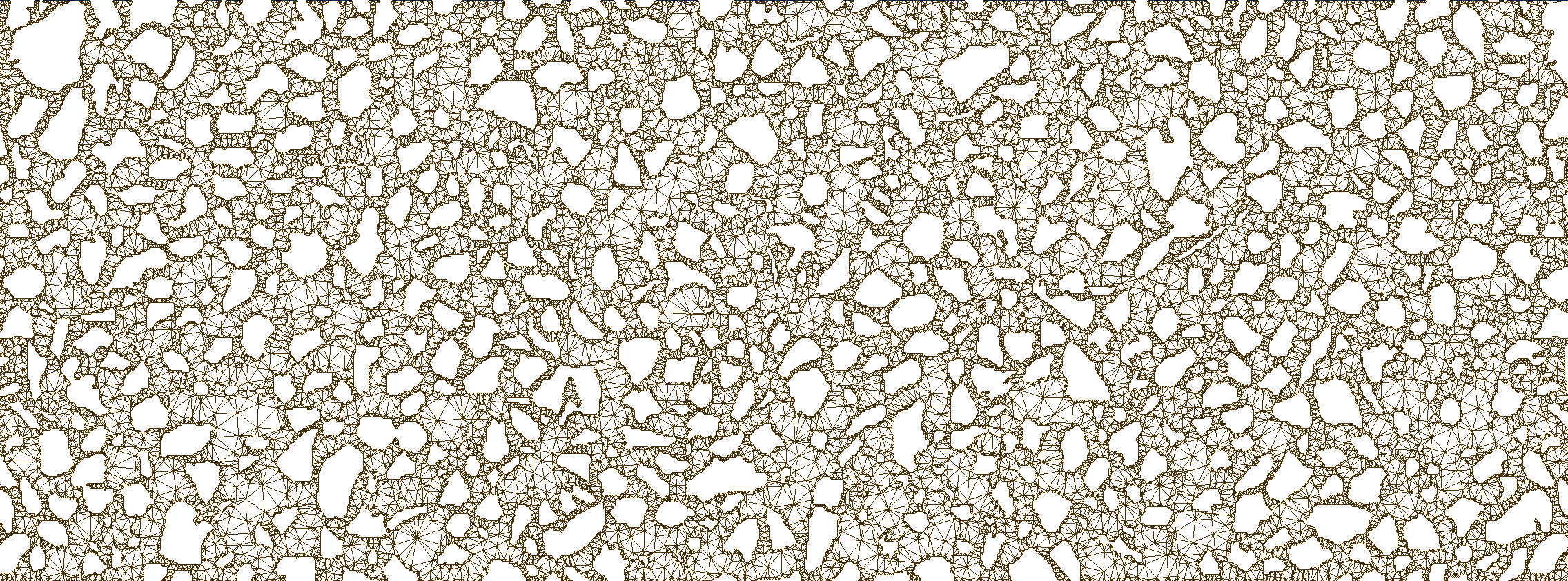
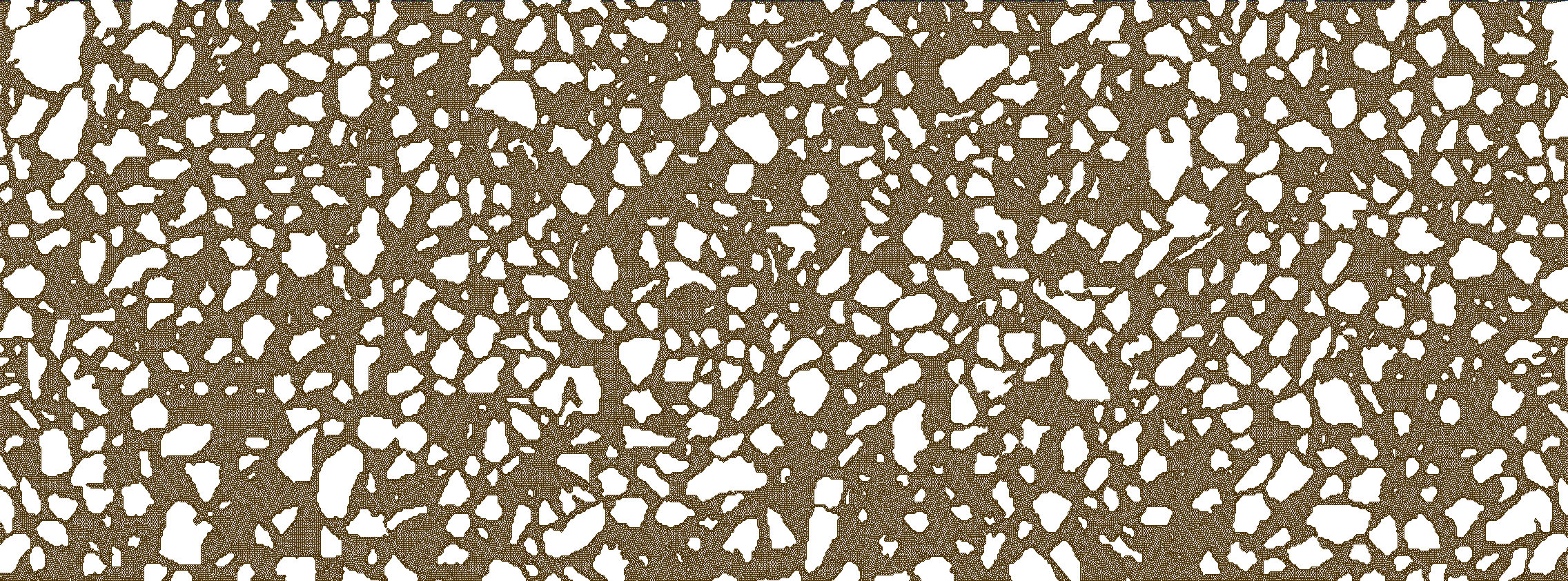
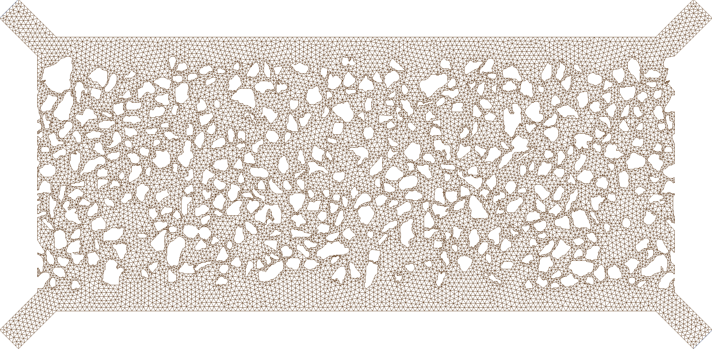
Let us consider the image below (this image and the real dimensions can be extracted from Fig. 52 in Benali2019 and Fig. 1c in Liu2022).

Grains and pore space configuration.
This image (2D) consists of 805x252 pixels, and the real dimensions (3D) are 6.74e-3 x 2.5e-3 x 0.03e-3 [m]. We remark that the image of the pattern used in the numerical simulations in Liu2022 has a much higher resolution.
The current implementation allows for the following input parameters:
 1#Set the pymm parameters
 2lenght = 6.74e-3      #Image-related, length of the microsystem [m]
 3width = 2.5e-3        #Image-related, height of the microsystem [m]
 4tickness = 0.03e-3    #Image-related, depth of the microsystem [m]
 5grainMeaning = 1      #Image-related, 0 if the grains in the image are light colors (e.g., white) or 1 for dark colors (e.g., black)
 6threshold = 0.5       #Image-related, threshold for converting the image to binary
 7rescale = 1           #Image-related, rescaled factor for the input image
 8grainsSize = 0        #Image-related, minimum size of the grain clusters
 9borderTol = 0         #Image-related, tolerance to approximate the border as polygon
10grainsTol = 0         #Image-related, tolerance to approximate the grains as polygon
11lineWidth = 1         #Figure-related, line width to show the contours in the produced figures
12channelWidth = 0.2e-3 #Device-related, width of the top and bottom channels in the micromodel device [m]
13meshSize = 8e-6       #Mesh-related, mesh size [m]
14viscocity = 1e-6      #Fluid-related, kinematic viscosity [dynamic viscosity/fluid_density, m2/s]
15diffusion = 1e-12     #Fluid-related, diffusion coefficient for the tracer [m2/s]
16inletLocation = "top" #Simulation-related, inlet bc location (left, top, right, or bottom)
17inletValue = 5.0e-4   #Simulation-related, inlet bc value (pressure/fluid_density, [Pa/(kg/m3)])
18tracerTime = 120      #Simulation-related, end time for the tracer simulation [s]
19tracerWrite = 1       #Simulation-related, time interval to write the tracer results [s]
20pressureConv = 1e-7   #Solver-related, convergence criterium for the pressure solution in the numerical scheme for the Stokes simulation
21velocityConv = 1e-8   #Solver-related, convergence criterium for the velocity solution in the numerical scheme for the Stokes simulation
22iterationsMax = 10000 #Solver-related, maximum number of iterations for the Stokes simulation in case the convergence criteria have not been reached
23tracerStep = 1        #Solver-related, time step in the numerical scheme for the tracer simulation [s]
Remaining parameters
The remaining parameters are OpenFOAM related. For example, inletLocation sets the side where the fluid is injected, and for the device, ‘top’ corresponds to the left top entry, ‘right’ to the top right entry, etc. Refer to the online OpenFOAM resources for details about the simulator and this nice presentation using the OpenFOAM solver simpleFoam in another micromodel application. Details about the solver simpleFoam and mathematical model can be found in this link. Details about the solver scalarTransportFoam and mathematical model can be found here.


