5. Modify the physical model and grid#
Goal#
Explore geometry, resolution, transport, or solver settings.
Configuration#
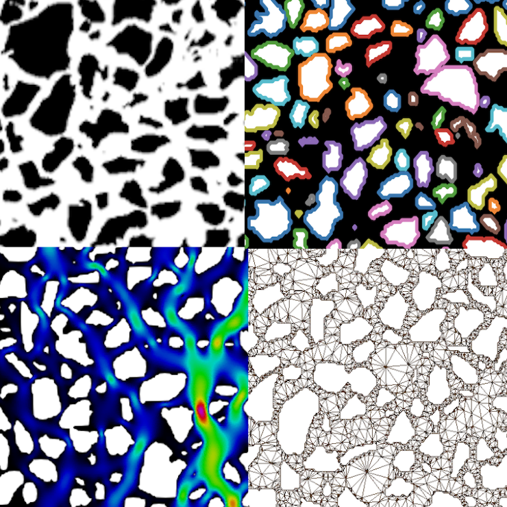
The systems in this tutorial were generated using meshSize = 8e-6 m,
borderTol = 0, and grainsTol = 0. The inlet boundary was placed at the
top using inletLocation = "top".
Change one parameter at a time to evaluate its effect. For example, decrease
meshSize for a finer mesh, adjust borderTol and grainsTol to
change the level of detail retained during border and grain extraction, or
change inletLocation to select another injection side.
The configuration reference includes images showing the effect of different meshSize values on the generated grid and different borderTol and grainsTol values on the extracted borders and grain contours. Consult these examples before selecting values for a new image.
Command#
pymm -i microsystem.png -p parameters.toml -t mesh_flow
How it works#
mesh_flow rebuilds the image-derived mesh and then recomputes the steady
flow field. See the configuration reference for
accepted values, units, and illustrated parameter examples.
Result#
Compare the new mesh and VTK data with the previous output directory. Use
meshSize = 8e-6 m, borderTol = 0, and grainsTol = 0 as the
baseline values. Inspect the generated mesh when changing meshSize and the
extracted border and grain contours when changing borderTol or
grainsTol.
Next#
Continue with 6. Run the complete workflow.